|
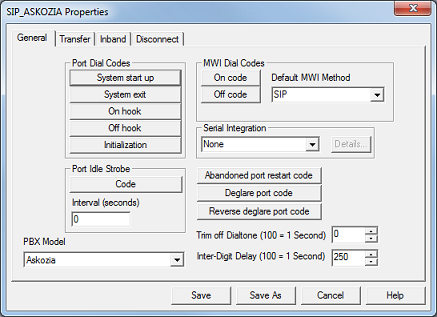
The General tab, shown below, contains any settings that did not fit into the other three categories.
Note: If you are using a non-SIP system, the PBX Model setting will not be displayed, as it only is used for SIP-enabled systems.

Most of the settings on this tab consist of short scripts that describe the steps taken by the system in response to the given event. These scripts are edited using the PBX Code Editor.
Port Dial Codes
Setting
|
Description
|
System start up
|
Specifies the dial code sent to the PBX at startup.
|
System exit
|
Specifies the dial code sent to the PBX at system shutdown.
|
On hook
|
Specifies the dial code to create an on hook condition.
|
Off hook
|
Specifies the dial code to create an off hook condition.
|
Initialization
|
Specifies the dial code to use each time a line is initialized (that is, when a caller hangs up).
|
Port Idle Strobe
Setting
|
Description
|
Code
|
Specifies the dial code to send to the PBX periodically while the line is idle.
|
Interval (1 ms)
|
Specifies the interval, in milliseconds, at which the idle strobe code is sent.
|
MWI Dial Codes
Setting
|
Description
|
On code
|
Species the dial code sent to the PBX to turn off the message light for an extension.
|
Off code
|
Species the dial code sent to the PBX to turn on the message light for an extension.
|
Default MWI method
|
Species the signalling method used to enable or disable the message light for any MWI notification where the notification template being used has the method set as PBX Default. If the notification template has the method set to any other option, then that setting will override the setting in the PBX template.
See below for the list of MWI method types.
|
As noted in the table above, the default MWI method setting provides several options. They include:
MWI Type
|
Description
|
HTTP, HTTP + PMS
|
The system sends the MWI notification via the HTTP Name Service.
If HTTP + PMS is selected, a message count or MWI status packet will be sent to the PMS as well, assuming the PMS protocol supports it.
|
Inband, Inband + PMS
|
The system dials DTMF codes over the voice line to perform the notification. This is the default method.
If Inband + PMS is selected, a message count or MWI status packet will be sent to the PMS as well, assuming the PMS protocol supports it.
|
PMS Only
|
The system only notifies the PMS, via the PMS link, and not the PBX. This is for sites where the PMS controls the MWI lights itself rather than the VMS.
For this to work, the PMS protocol in use must support receiving message count or MWI status packets from the VMS.
|
Serial, Serial + PMS
|
The system notifies the PBX over a serial link. Do not use this method for the Hitachi PBX; in that case, the method should be PMS Only.
If Serial + PMS is selected, a message count or MWI status packet will be sent to the PMS as well, assuming the PMS protocol supports it.
|
SIP, SIP + PMS
|
The system sends a SIP notify packet to the PBX and lets the PBX notify the endpoint (phone). SIP only.
|
SIPG, SIPG + PMS
|
The system sends a SIP notify packet to the gateway device (e.g., DMG) which passes the notification on to the PBX. SIP only, and only if using a gateway.
This option requires that you define the Gateway address in each mailbox, which is the IP address of the gateway device that will receive the notification. It will also use the address defined in the appropriate notification templates (by default address MWI 0 is the one used, but the templates can be edited to use a different address).
If SIPG + PMS is selected, a message count or MWI status packet will be sent to the PMS as well, assuming the PMS protocol supports it.
|
SIPX, SIPX + PMS
|
The system sends a SIP notify packet directly to the endpoint (phone). SIP only.
This option requires that you define a SIPAddress in the address list for each mailbox and modify the MWI on and off notification templates to use that address (e.g., SIPAddress 0).
If SIPX + PMS is selected, a message count or MWI status packet will be sent to the PMS as well, assuming the PMS protocol supports it.
|
TAPI, TAPI + PMS
|
The system notifies the PBX via a TAPI link. This is only supported when integrating with an Avaya IP Office via TAPI.
If TAPI + PMS is selected, a message count or MWI status packet will be sent to the PMS as well, assuming the PMS protocol supports it.
|
Serial Integration
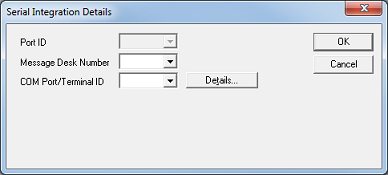
Use the drop-down list to select an integration. If anything other than None is selected, click Details to open a dialog to view or edit the properties of the selected serial integration, as shown below.

The Serial Integration Details dialog displays the following settings:
Setting
|
Description
|
Port ID
|
This setting is automatically assigned on a per-port basis. If necessary, you can change it by editing each port directly via the port configuration dialog.
|
Message Desk Number
|
Specifies the identifier sent by the switch, as part of the serial data packet, to indicate which device the packet is intended for (theoretically, devices other than the VMS may be receiving SMDI information from the switch over the same connection).
|
COM Port/Terminal ID
|
Specifies the COM port used by the serial integration. If the port does not exist on the system, you will be prompted to create it. Click Details to review the port properties after it has initially been set up.
|
Other Settings
Setting
|
Description
|
PBX Model
|
SIP only. This setting is used by the system to identify which specific SIP PBX is connected to it and is not displayed on non-SIP systems.
|
Abandoned port restart code
|
Specifies the dial code sent to the PBX to recover a line.
|
Deglare port code
|
Specifies the dial code used to verify that a port is free before the system attempts to outdial. Typically, it will look for dial tone for a specified length of time.
|
Reverse deglare port code
|
Specifies the dial code used if the system determines that it cannot outdial and must return the line to a normal processing state.
|
Trim off dial tone
|
Specifies how much to trim off the end of a message recording that ends on dial tone. Intended for systems that do not provide positive disconnect (e.g., loop current drop). The value is expressed in 10 millisecond increments, so a value of 100 would equal 1000 ms (1 second). The valid range is 0 to 9999, and the default is 0.
|
Inter-digit delay
|
Specifies how long to wait for each subsequent DTMF digit after the first one. Value is expressed in 10 millisecond increments, so a value of 250 equals 2500 ms (which is 2.5 seconds). The valid range is 250 to 9999, and the default is 250.
|
|


